![[C# Helper]](https://waybackassets.bk21.net/20140505160937im_/http://www.csharphelper.com/banner128x128.png)
|
![[Essential Algorithms]](https://waybackassets.bk21.net/20140505160937im_/http://www.csharphelper.com/essential_algs_t.jpg)
|
![[MCSD Certification Toolkit (Exam 70-483): Programming in C#]](https://waybackassets.bk21.net/20140505160937im_/http://www.csharphelper.com/c_cert_112x140.jpg)
|
![[C# 24-Hour Trainer]](https://waybackassets.bk21.net/20140505160937im_/http://www.csharphelper.com/24hour_t.jpg)
|
BLOG.CSHARPHELPER.COM
Render text in a WPF program using C#
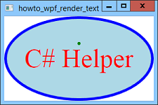 Normally to display text in WPF you use some sort of object such as a Label or TextBlock, but you can draw text yourself if necessary. To make this easier, at design time I set the window's Background property to Transparent (otherwise the window draws the background on top of any text you draw). I also named the main control control grdMain to make it easy to tell how big the window's client area is.
To draw the text, override the window's OnRender method and use its drawingContext parameter to do the drawing. This program uses the following OnRender method.
Normally to display text in WPF you use some sort of object such as a Label or TextBlock, but you can draw text yourself if necessary. To make this easier, at design time I set the window's Background property to Transparent (otherwise the window draws the background on top of any text you draw). I also named the main control control grdMain to make it easy to tell how big the window's client area is.
To draw the text, override the window's OnRender method and use its drawingContext parameter to do the drawing. This program uses the following OnRender method.
protected override void OnRender(DrawingContext drawingContext)
{
    // Clear the background and draw an ellipse.
    DrawEllipse(drawingContext);

    // Make the FormattedText object.
    Typeface typeface = new Typeface("Times New Roman");
    double em_size = 40;
    FormattedText formatted_text = new FormattedText(
        "FormattedText", CultureInfo.CurrentUICulture,
        FlowDirection.LeftToRight,
        typeface, em_size, Brushes.Red);

    // Center the text horizontally.
    formatted_text.TextAlignment = TextAlignment.Center;

    // Find the center of the client area.
    double xmid = grdMain.ActualWidth / 2;
    double ymid = grdMain.ActualHeight / 2;
    Point center = new Point(xmid, ymid - formatted_text.Height / 2);

    // Draw the text.
    drawingContext.DrawText(formatted_text, center);

    // Draw an ellipse at the text's drawing point.
    drawingContext.DrawEllipse(Brushes.Green, null, center, 3, 3);
}
This method starts by calling the DrawEllipse method to draw an ellipse that fills the window. See the example Render an ellipse in a WPF program using C# for information about how that method works.
Next the code creates a Typeface object to represent the font to use, in this case Times New Roman. It then uses the Typeface to create a FormattedText object. That object represents a particular piece of text drawn with a specific brush. The FormattedText constructor takes as a parameter the culture that should be used to draw the text. This example simply uses the current program's user interface culture.
The FormattedText object includes information about how the text should be drawn such as the brush to use. It also provides properties and methods to let you control the text formatting in other ways. This example sets the object's TextAlignment property to center the text horizontally.
Unlike the StringFormat class in GDI+ (see the example Use a StringFormat object and a Rectangle to align painted text in C#), the TextAlignment property doesn't give you any control over the text's vertical alignment. To align text vertically, you need to measure the text and calculate the proper Y coordinate.
This example uses the size of the grdMian control to find the center of the window's client area. It then subtracts half the formatted text's height from the Y coordinate to center the text vertically.
The code then calls the DrawingContext object's DrawText method to draw the text. Finally the method draws a small green ellipse to show the text's reference point, the point passed into the DrawText method.


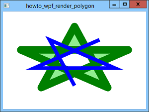
Render polygons and polylines in a WPF program using C#
 WPF lets you do all sorts of interesting things that are much harder in Windows Forms applications. However sometimes, as in this example, it makes simple things much harder. Perhaps they're trying to "gently" encourage us to use drawing objects (such as the Polygon object) to draw shapes instead of trying to render them on your own. It is definitely easier to use that approach. If that was Microsoft's idea, it might have been better if they just didn't allow this kind of rendering instead of giving us a confusing and poorly-documented method for doing it.
Anyway, with the rant out of the way, let me explain how the program works. The DrawingContext class provides a few drawing methods such as DrawEllipse, DrawLine, and DrawRectangle. Logically that class should also provide DrawPolygon, DrawPolyline, and other drawing methods, so for this example I decided to add them as extension methods. The following code shows the private DrawPolygonOrPolyline method that draws either polygons or polylines.
WPF lets you do all sorts of interesting things that are much harder in Windows Forms applications. However sometimes, as in this example, it makes simple things much harder. Perhaps they're trying to "gently" encourage us to use drawing objects (such as the Polygon object) to draw shapes instead of trying to render them on your own. It is definitely easier to use that approach. If that was Microsoft's idea, it might have been better if they just didn't allow this kind of rendering instead of giving us a confusing and poorly-documented method for doing it.
Anyway, with the rant out of the way, let me explain how the program works. The DrawingContext class provides a few drawing methods such as DrawEllipse, DrawLine, and DrawRectangle. Logically that class should also provide DrawPolygon, DrawPolyline, and other drawing methods, so for this example I decided to add them as extension methods. The following code shows the private DrawPolygonOrPolyline method that draws either polygons or polylines.
// Draw a polygon or polyline.
private static void DrawPolygonOrPolyline(
    this DrawingContext drawingContext,
    Brush brush, Pen pen, Point[] points, FillRule fill_rule,
    bool draw_polygon)
{
    // Make a StreamGeometry to hold the drawing objects.
    StreamGeometry geo = new StreamGeometry();
    geo.FillRule = fill_rule;

    // Open the context to use for drawing.
    using (StreamGeometryContext context = geo.Open())
    {
        // Start at the first point.
        context.BeginFigure(points[0], true, draw_polygon);

        // Add the points after the first one.
        context.PolyLineTo(points.Skip(1).ToArray(), true, false);
    }

    // Draw.
    drawingContext.DrawGeometry(brush, pen, geo);
}
This method creates a StreamGeometry object to represent the shape. The StreamGeometry class is a geometry class (there are others such as LineGeometry and RectangleGeometry) that represents a sequence of drawing commands that can include shapes such as lines, arcs, ellipses, and rectangles. (The PathGeometry class is similar but heavier because it supports data binding, animation, and modification. Because this example doesn't need those, it uses the lighter-weight StreamGeometry class.)
After it creates the StreamGeometry object, the code sets its FillRule property. This can have the values EvenOdd or Nonzero. This example uses the EvenOdd setting so there is an unfilled hole in the middle of the green outer star. (See the picture.) If this was set to Nonzero, then the interior of the star would be filled completely.
Next the program "opens" the StreamGeometry to get a context that it can use to draw. It calls the context's BeginFigure method to start a drawing sequence. You need to call this method before you start drawing. Its first parameter indicates where drawing should start, in this case at the points array's first point.
The second parameter to BeginFigure indicates whether the shape should be filled. This example sets this value to true. If you don't want to fill the shape, you can simply pass this method a null brush to make the method "fill" the shape with nothing.
The final parameter to BeginFigure indicates whether the shape should be closed. The method uses the value of its draw_polygon parameter so this code closes the shape only if it is drawing a polygon.
After starting a new figure, the code calls the context's PolyLineTo method. Its first parameter is the array of points that should be connected. Unfortunately if the first point in the array duplicates the point used in the call to BeginFigure, then the polyline includes that point twice and that messes up the connection between the last point and the first point. For example, if the green star used mitered instead of rounded corners, then the final corner between the first and last point would not be mitered. (To see the effect, pass the entire points array in here and change the main program to not use rounded corners.)
To work around this problem, the code uses the LINQ Skip extension method to skip the first point in the points array and only pass the rest of the points into the call to PolyLineTo.
The second parameter to PolyLineTo determines whether the line segments between the points in the polyline should be "stroked" (drawn). This example sets this to true so the points are always drawn. If you don't want to draw the line segments, simply pass the method a null pen to make method "draw" them with nothing.
The final parameter to PolyLineTo indicates whether the lines should be joined smoothly. The example sets this value to false. If you want the lines joined smoothly, you can specify the pen's LineJoin property to Rounded. (Described shortly.)
Finally, after those short but hard-to-explain steps, the program calls the DrawingContext obect's DrawGeometry method to draw the StreamGeometry containing the polygon or polyline.
The DrawPolygonOrPolyline method is declared private so it is only visible inside the static DrawingContextExtensions class that defines it. You could make it public, but then the main program would need to use the same method to draw both polygons and polylines. While that wouldn't be the end of the world, it's usually better to make a method perform a single well-defined task instead of making one super-method that does a lot.
Instead of making this method public, I created the following two public methods that call the private one.
// Draw a polygon.
public static void DrawPolygon(this DrawingContext drawingContext,
    Brush brush, Pen pen, Point[] points, FillRule fill_rule)
{
    drawingContext.DrawPolygonOrPolyline(brush, pen, points, fill_rule, true);
}

// Draw a polyline.
public static void DrawPolyline(this DrawingContext drawingContext,
    Brush brush, Pen pen, Point[] points, FillRule fill_rule)
{
    drawingContext.DrawPolygonOrPolyline(brush, pen, points, fill_rule, false);
}
Now using these methods from the main program is just easy as using the other methods provided by the DrawingContext class. The following code show how the program draws the green star.
// Draw the polygon.
Pen pen = new Pen(Brushes.Green, line_thickness);
pen.LineJoin = PenLineJoin.Round;
drawingContext.DrawPolygon(Brushes.LightGreen,
    pen, points, FillRule.EvenOdd);
This code creates a pen and sets its LineJoin property to Rounded. It then calls the DrawPolygon extension method, passing it a light green brush, the pen, the points (defined earlier in code that isn't interesting enough to show), and the desired fill rule.
The following code shows how the program draws the smaller blue polyline.
// Draw the polyline.
pen = new Pen(Brushes.Blue, line_thickness / 2);
drawingContext.DrawPolyline(null, pen,
    points, FillRule.EvenOdd);
This code creates a new pen. It calls the DrawPolyline extension method, passing it a null brush (so the shape isn't filled), the pen, the points (re-defined earlier in code that isn't interesting enough to show), and the desired fill rule.
If you look back at the DrawPolygonOrPolyline method, you'll see that the code isn't really all that hard. It was just hard to find out how to do this. And I do wonder why Microsoft didn't include simple methods such as this one in WPF to begin with. At least making this an extension method makes it as easy to use as the other DrawingContext methods.
Render dashed lines in a WPF program using C#
 When you draw in WPF, you create a Pen object. You can set that object's DashStyle to make the pen draw dashed or dotted lines. The following code shows how this example draws the second line from the top.
Pen dashed_pen = new Pen(Brushes.Blue, line_thickness);
dashed_pen.DashStyle = DashStyles.Dash;
drawingContext.DrawLine(dashed_pen, point1, point2);
The DashStyles enumeration defines the styles Dash, DashDot, DashDotDot, Dot, and Solid. Sometimes you may want to define your own dash styles. For example, in a dashed line with a thickness of one pixel, the dashes are very small and the spaces between them are even smaller. After WPF finishes anti-aliasing the Dot style to make things look smoother, the result appears to be a fuzzy but solid line that doesn't seem to have any breaks in it. In those cases, you may want to use a custom dash style. For example, skipping 5 pixels and then drawing 5 pixels produces a nice easy-to-see dash style for a thin line. The following code shows how the program creates its first custom line (drawn in green).
Pen custom1_pen = new Pen(Brushes.Green, line_thickness);
DashStyle dash_style1 = new DashStyle(
    new double[] { 5, 5 }, 0);
custom1_pen.DashStyle = dash_style1;
drawingContext.DrawLine(custom1_pen, point1, point2);
This code creates a green Pen. It then makes a new DashStyle object, passing its constructor an array of doubles that defines the dash pattern. The values in the array indicate the distance drawn and then skipped as multiples of the line's thickness. The values are adjusted by the dash cap at the ends of each dash, so the dashes tend to get a bit of extra length and the gaps between them shrink a bit. When WPF anti-aliases the result to make it smoother, it also makes the edges of the dashes a bit fuzzy, so the exact sizes won't be exactly what you specify.
The following code shows how the example creates its last custom dash pattern.
Pen custom3_pen = new Pen(Brushes.Green, line_thickness);
DashStyle dash_style3 = new DashStyle(
    new double[] { 3, 2, 3, 2, 0, 2 }, 0);
custom3_pen.DashStyle = dash_style3;
drawingContext.DrawLine(custom3_pen, point1, point2);
This is similar to the previous code except it specifies a longer sequence of dashes and gaps to make a dash-dash-dot pattern.
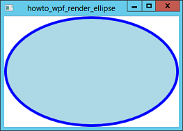
Render an ellipse in a WPF program using C#
 Normally to draw shapes in WPF you use some sort of object. You can add Ellipse, Line, Path, Polygon, Polyline, and Rectangle objects to a window and those shapes redraw themselves when necessary.
However, sometimes you may want to draw on a window at runtime without creating those kinds of objects. WPF doesn't provide a Paint event the way Windows Forms do, so that's not where you put your code. Instead you should override the window's (or other control's) OnRender method. That method provides a DrawingContext parameter named drawingContext that you can use to draw (much as a Paint event handler provides a Graphics object that you can use to draw). Drawing inside the OnRender method is reasonably simple, although there are a couple of catches.
First, if you're drawing on the window, you need to set the window's Background property to Transparent. If you don't, then the window seems to draw its background after the OnRender method is called so whatever you drawn doesn't appear.
Second, I have yet to figure out a good way to determine the size of the window's client area--its area without borders, title bar, menu, and so forth. Fortunately that's easy enough to work around. Just get the size of the window's main content object, which by default is a Grid control. To make that easy, in this example I set the main Grid control's Name to grdMain. Then the code can just use grdMain.ActualWidth and grdMain.ActualHeight to get the client area dimensions.
The following code shows how the program draws an ellipse whenever the form is rendered.
Normally to draw shapes in WPF you use some sort of object. You can add Ellipse, Line, Path, Polygon, Polyline, and Rectangle objects to a window and those shapes redraw themselves when necessary.
However, sometimes you may want to draw on a window at runtime without creating those kinds of objects. WPF doesn't provide a Paint event the way Windows Forms do, so that's not where you put your code. Instead you should override the window's (or other control's) OnRender method. That method provides a DrawingContext parameter named drawingContext that you can use to draw (much as a Paint event handler provides a Graphics object that you can use to draw). Drawing inside the OnRender method is reasonably simple, although there are a couple of catches.
First, if you're drawing on the window, you need to set the window's Background property to Transparent. If you don't, then the window seems to draw its background after the OnRender method is called so whatever you drawn doesn't appear.
Second, I have yet to figure out a good way to determine the size of the window's client area--its area without borders, title bar, menu, and so forth. Fortunately that's easy enough to work around. Just get the size of the window's main content object, which by default is a Grid control. To make that easy, in this example I set the main Grid control's Name to grdMain. Then the code can just use grdMain.ActualWidth and grdMain.ActualHeight to get the client area dimensions.
The following code shows how the program draws an ellipse whenever the form is rendered.
protected override void OnRender(DrawingContext drawingContext)
{
    // Clear the background.
    Rect bg_rect = new Rect(0, 0, this.ActualWidth, this.ActualHeight);
    drawingContext.DrawRectangle(Brushes.White, null, bg_rect);

    // Make the pen to outline the ellipse.
    const double pen_width = 5;
    Pen pen = new Pen(Brushes.Blue, pen_width);

    // Get the center of the content Grid control.
    double center_x = grdMain.ActualWidth / 2;
    double center_y = grdMain.ActualHeight / 2;
    Point center = new Point(center_x, center_y);

    // Subtract half the width of the pen from
    // the center to get radius_x and radius_y
    // so the ellipse just touches the sides of the form.
    double radius_x = center_x - pen_width / 2;
    double radius_y = center_y - pen_width / 2;

    // Draw the ellipse.
    drawingContext.DrawEllipse(Brushes.LightBlue,
        pen, center, radius_x, radius_y);
}
First the code draws a white rectangle on the form to clear its background and then creates a blue pen. Notice that in WPF you pass the Pen constructor a brush not simply a color. This is because WPF fills lines instead of just drawing them. That seems odd if you're using one pixel wide lines to draw shapes, but WPF drawings are scalable. If you zoom in on a drawing, lines become thicker and then you might be able to see a shading or patterns in the line's brush. (This still seems a bit odd to me. Lots of programs draw solid lines. It's strange that WPF provides standard solid brushes but not standard solid lines.)
Note also that WPF's Pen class does not have a Dispose method so you cannot dispose pens or create them in using statements.
After it builds its pen, the program calculates the center of the client area. It subtracts half of the pen's width from the client area's width and height so the ellipse will just touch the window's edges, and then uses the DrawingContext object's DrawEllipse method to draw the ellipse.
Let the user select and deselect objects in a 3D program that uses WPF, XAML, and C#
 The example Perform hit testing in a 3D program that uses WPF, XAML, and C# shows how to tell when the user clicks an object in a 3D WPF program. This example uses similar techniques to let the user select and deselect objects.
This program contains several refinements over previous 3D WPF examples. In particular, its static MeshExtensions class includes more methods for adding simple shapes to a mesh. This example uses the AddBox extension method to add a bunch of cubes to the 3D model. That method simply creates the triangles needed to build a box. It's straightforward so it isn't shown here.
The following code shows how the program builds its three-dimensional objects.
The example Perform hit testing in a 3D program that uses WPF, XAML, and C# shows how to tell when the user clicks an object in a 3D WPF program. This example uses similar techniques to let the user select and deselect objects.
This program contains several refinements over previous 3D WPF examples. In particular, its static MeshExtensions class includes more methods for adding simple shapes to a mesh. This example uses the AddBox extension method to add a bunch of cubes to the 3D model. That method simply creates the triangles needed to build a box. It's straightforward so it isn't shown here.
The following code shows how the program builds its three-dimensional objects.
// The currently selected model.
private GeometryModel3D SelectedModel = null;

// Materials used for normal and selected models.
private Material NormalMaterial, SelectedMaterial;

// The list of selectable models.
private List<GeometryModel3D> SelectableModels =
    new List<GeometryModel3D>();

// Add the model to the Model3DGroup.
private void DefineModel(Model3DGroup model_group)
{
    // Make the normal and selected materials.
    NormalMaterial = new DiffuseMaterial(Brushes.LightGreen);
    SelectedMaterial = new DiffuseMaterial(Brushes.Red);

    // Create some cubes.
    for (int x = -5; x <= 3; x += 4)
    {
        for (int y = -5; y <= 3; y += 4)
        {
            for (int z = -5; z <= 3; z += 4)
            {
                // Make a cube with lower left corner (x, y, z).
                MeshGeometry3D mesh = new MeshGeometry3D();
                mesh.AddBox(x, y, z, 2, 2, 2);
                GeometryModel3D model = new GeometryModel3D(mesh, NormalMaterial);
                model_group.Children.Add(model);

                // Remember that this model is selectable.
                SelectableModels.Add(model);
            }
        }
    }

    // X axis.
    MeshGeometry3D mesh_x = MeshExtensions.XAxis(6);
    model_group.Children.Add(mesh_x.SetMaterial(Brushes.Red, false));

    // Y axis.
    MeshGeometry3D mesh_y = MeshExtensions.YAxis(6);
    model_group.Children.Add(mesh_y.SetMaterial(Brushes.Green, false));

    // Z axis.
    MeshGeometry3D mesh_z = MeshExtensions.ZAxis(6);
    model_group.Children.Add(mesh_z.SetMaterial(Brushes.Blue, false));
}
The code first defines the variable SelectedModel to store a reference to the object that it currently selected. Initially it sets that object to null.
Next the program defines two materials: one to use for normal objects and one to use for selected objects. It then makes a List to hold the models that will be selectable.
The DefineModel method starts by initializing the normal and selected material. It then uses three nested for loops to create 27 cubes. It gives them all the normal material and saves them in the SelectableModels list.
The method then uses the static XAxis, YAxis, and ZAxis methods to add axis arrows to the model. Note that it doesn't save those objects in the SelectableModels list.
When the user clicks on the viewport, the following code executes.
// See what was clicked.
private void MainViewport_MouseDown(object sender, MouseButtonEventArgs e)
{
    // Deselect the prevously selected model.
    if (SelectedModel != null)
    {
        SelectedModel.Material = NormalMaterial;
        SelectedModel = null;
    }

    // Get the mouse's position relative to the viewport.
    Point mouse_pos = e.GetPosition(MainViewport);

    // Perform the hit test.
    HitTestResult result =
        VisualTreeHelper.HitTest(MainViewport, mouse_pos);

    // See if we hit a model.
    RayMeshGeometry3DHitTestResult mesh_result =
        result as RayMeshGeometry3DHitTestResult;
    if (mesh_result != null)
    {
        GeometryModel3D model = (GeometryModel3D)mesh_result.ModelHit;
        if (SelectableModels.Contains(model))
        {
            SelectedModel = model;
            SelectedModel.Material = SelectedMaterial;
        }
    }
}
The code begins by deselecting the previously selected model. If SelectedModel is not null, the code sets that model's Material property to the normal material. It then sets SelectedModel to null.
Next the method gets the mouse's current position and performs the hit test. If the test hit an object, the program gets the GeometryModel3D object that was hit. If that model is in the SelectableModels list, the code saves a reference to the object in the SelectedModel variable and sets the model's Material to the selected material.
That's about all there is to this example. The rest of the details are the same as those used in previous examples. You can download the code to see how they work.
In a more complicated program such as a game, you would probably need to do more than just change the selected object's material to show that it is selected. For example, you might need to look up the clicked object to see what it is. Then if it's a door, potion, or medallion, the program can take appropriate action. To do that, you could replace the SelectableModels list with a dictionary that uses models as keys and some sort of class or structure as values. When the user clicks an object, you could look it up in the dictionary to get the associated data so you could figure out what to do.
Because dictionaries are so fast, that would even be more efficient than this version that uses SelectableModels list, at least if you have a lot of selectable objects.
Remove a selected part of an image in C#

// Make an image that includes only the selected area.
private Bitmap MakeImageWithArea(Bitmap source_bm, List<Point> points)
{
    // Copy the image.
    Bitmap bm = new Bitmap(source_bm.Width, source_bm.Height);

    // Clear the selected area.
    using (Graphics gr = Graphics.FromImage(bm))
    {
        gr.Clear(Color.Transparent);

        // Make a brush that contains the original image.
        using (Brush brush = new TextureBrush(source_bm))
        {
            // Fill the selected area.
            gr.FillPolygon(brush, points.ToArray());
        }
    }
    return bm;
}
The method first creates a new bitmap that has the same dimensions as the source bitmap. It creates a Graphics object associated with the new bitmap and uses it to clear the bitmap, filling it with the Transparent color.
Next the code makes a TextureBrush. A TextureBrush fills objects with a repeating image. In this case, the program uses the source bitmap as the brush's image. It then simply fills the selected area with the brush. The method then returns the new bitmap.
The code that creates an image with the selected area removed is a bit trickier. Ideally you would just start with a copy of the original bitmap and then fill the selected area with the Transparent color. Unfortunately when you draw, the program overlays the new color on top of the image's existing colors. For example, if you draw with a 50% opaque color, the area drawn is only shaded by the partly opaque color. In this example, if you fill an area with a Transparent color, the area is completely unaffected.
You could fill the area with some unusual color and then use the bitmap's MakeTransparent method to make pixels with that color transparent. For example, you could use magenta or the color with RGB components 1, 1, 1, and hope the original image doesn't contain any pixels with that color. However, there's always a chance that the image does contain that color and then the program would make stray pixels transparent.
Instead of using MakeTransparent, the program uses a different approach, which is shown in the following code.
// Make an image that includes only the selected area.
private Bitmap MakeImageWithoutArea(Bitmap source_bm, List<Point> points)
{
    // Copy the image.
    Bitmap bm = new Bitmap(source_bm);

    // Clear the selected area.
    using (Graphics gr = Graphics.FromImage(bm))
    {
        GraphicsPath path = new GraphicsPath();
        path.AddPolygon(points.ToArray());
        gr.SetClip(path);
        gr.Clear(Color.Transparent);
        gr.ResetClip();
    }
    return bm;
}
This code makes a copy of the original bitmap and creates a Graphics object associated with it. Next it creates a GraphicsPath object and adds the selected area's points to it as a polygon. It calls the Graphics object's SetClip method to restrict drawing operations to the GraphicsPath, and then uses the Graphics object's Clear method to clear the bitmap with the Transparent color. Because SetClip restricts drawing to the selected area, this clears only the selected area.
After clearing the selected area, the code resets the bitmap's clipping region and returns the bitmap.
The program has one more interesting piece of code. The MakeSampleImage method shown in the following code takes a bitmap as a parameter and draws it on top of a checkerboard pattern so you can see any transparent areas in the image.
// Make a sample showing transparent areas.
private Bitmap MakeSampleImage(Bitmap bitmap)
{
    const int box_wid = 20;
    const int box_hgt = 20;

    Bitmap bm = new Bitmap(bitmap.Width, bitmap.Height);
    using (Graphics gr = Graphics.FromImage(bm))
    {
        // Start with a checkboard pattern.
        gr.Clear(Color.White);
        int num_rows = bm.Height / box_hgt;
        int num_cols = bm.Width / box_wid;
        for (int row = 0; row < num_rows; row++)
        {
            int y = row * box_hgt;
            for (int col = 0; col < num_cols; col++)
            {
                int x = 2 * col * box_wid;
                if (row % 2 == 1) x += box_wid;
                gr.FillRectangle(Brushes.LightBlue,
                    x, y, box_wid, box_hgt);
            }
        }

        // Draw the image on top.
        gr.DrawImageUnscaled(bitmap, 0, 0);
    }
    return bm;
}
The method first creates a bitmap with the appropriate size and make an associated Graphics object. It clears the bitmap with white and then uses nested for loops to draw a light blue checkerboard pattern.
The method then uses the Graphics object's DrawImageUnscaled method to draw the sample image on top and returns the bitmap.
The rest of the program is reasonably straightforward. Download it to see how it works.
Perform hit testing in a 3D program that uses WPF, XAML, and C#
 Many three-dimensional programs need to perform hit testing to determine when the user clicks on something. This example draws two interlocked tetrahedrons inside a cage. When you click on one of the objects, the program displays information about the object you hit.
The program takes action when it receives a MouseDown event. Unfortunately the Viewport3D control does not fire that event unless the user clicks on an object in the three-dimensional data. If the user clicks on the background, the event isn't raised.
You can work around this problem by placing the Viewport3D inside some other control such as a Border and then catching the MouseDown event provided by that control.
Even that solution has a catch. The Border doesn't doesn't raise its MouseDown event if it has a transparent background. (Presumably that's the same problem with the Viewport3D in the first place. It has a transparent background, so mouse clicks on it don't register.) You can solve the new problem by giving the Border a non-transparent background such as Black or White.
The following XAML code shows how this program defines its Border and Viewport3D controls.
Many three-dimensional programs need to perform hit testing to determine when the user clicks on something. This example draws two interlocked tetrahedrons inside a cage. When you click on one of the objects, the program displays information about the object you hit.
The program takes action when it receives a MouseDown event. Unfortunately the Viewport3D control does not fire that event unless the user clicks on an object in the three-dimensional data. If the user clicks on the background, the event isn't raised.
You can work around this problem by placing the Viewport3D inside some other control such as a Border and then catching the MouseDown event provided by that control.
Even that solution has a catch. The Border doesn't doesn't raise its MouseDown event if it has a transparent background. (Presumably that's the same problem with the Viewport3D in the first place. It has a transparent background, so mouse clicks on it don't register.) You can solve the new problem by giving the Border a non-transparent background such as Black or White.
The following XAML code shows how this program defines its Border and Viewport3D controls.
<Grid>
    <Border Grid.Row="0" Grid.Column="0" Background="White"
        MouseDown="MainViewport_MouseDown">
        <Viewport3D Grid.Row="0" Grid.Column="0" Name="MainViewport" />
    </Border>
</Grid>
When the user clicks on the Viewport3D, the program needs to figure out which object you clicked. To do that, it stores the objects it creates in the Models dictionary defined by the following code.
// A record of the 3D models we build.
private Dictionary<Model3D, string> Models =
    new Dictionary<Model3D, string>();
As it creates its models, the program adds each to the dictionary, as in the following code.
Models.Add(model1, "Green model");Later, when the user clicks on the Border, the following code performs the hit test.
// See what was clicked.
private void MainViewport_MouseDown(object sender, MouseButtonEventArgs e)
{
    // Get the mouse's position relative to the viewport.
    Point mouse_pos = e.GetPosition(MainViewport);

    // Perform the hit test.
    HitTestResult result =
        VisualTreeHelper.HitTest(MainViewport, mouse_pos);

    // Display information about the hit.
    RayMeshGeometry3DHitTestResult mesh_result =
        result as RayMeshGeometry3DHitTestResult;
    if (mesh_result == null) this.Title = "";
    else
    {
        // Display the name of the model.
        this.Title = Models[mesh_result.ModelHit];

        // Display more detail about the hit.
        Console.WriteLine("Distance: " +
            mesh_result.DistanceToRayOrigin);
        Console.WriteLine("Point hit: (" +
            mesh_result.PointHit.ToString() + ")");

        Console.WriteLine("Triangle:");
        MeshGeometry3D mesh = mesh_result.MeshHit;
        Console.WriteLine("    (" +
            mesh.Positions[mesh_result.VertexIndex1].ToString() + ")");
        Console.WriteLine("    (" +
            mesh.Positions[mesh_result.VertexIndex2].ToString() + ")");
        Console.WriteLine("    (" +
            mesh.Positions[mesh_result.VertexIndex3].ToString() + ")");
    }
}
This code gets the mouse's position relative to the viewport. It then calls the VisualTreeHelper class's static HitTest method to see what (if anything) was hit inside the MainViewport control.
The program then converts the result into a RayMeshGeometry3DHitTestResult object. If that object is null, the user clicked on the background instead of something in the model. In that case, the program clears the window's Title.
If the click did hit something, the program displays information about the hit. It uses the mesh result's ModelHit property as an index into the Models dictionary. The dictionary returns the hit model's name, and the program displays that name in the form's title bar.
Next the program displays more information about the hit. It displays:
- The distance from the viewing origin to the point of intersection with the mesh that was hit.
- The coordinates of the point of intersection.
- The vertices of the mesh triangle that contains the point of intersection.
Draw a more efficient three-dimensional Menger sponge fractal using a dictionary, WPF, XAML, and C#
 The example Draw a three-dimensional Menger sponge fractal using WPF, XAML, and C# shows how to build a Menger sponge. That example recursively chops up cubes until it reaches a desired level of recursion. At that point, it draws a cube.
This is reasonably easy to understand, but it requires a fair amount of duplicated drawing because many of the cubes share faces. In fact, if two cubes share a face, then neither of those instances of the face should be drawn.
This example uses a Dictionary to avoid drawing those shared faces. It was trickier than I thought it would be. That makes this post a bit long, but I think it's interesting.
To avoid drawing duplicated faces, the program uses three main techniques:
The example Draw a three-dimensional Menger sponge fractal using WPF, XAML, and C# shows how to build a Menger sponge. That example recursively chops up cubes until it reaches a desired level of recursion. At that point, it draws a cube.
This is reasonably easy to understand, but it requires a fair amount of duplicated drawing because many of the cubes share faces. In fact, if two cubes share a face, then neither of those instances of the face should be drawn.
This example uses a Dictionary to avoid drawing those shared faces. It was trickier than I thought it would be. That makes this post a bit long, but I think it's interesting.
To avoid drawing duplicated faces, the program uses three main techniques:
- An ApproxPoint class to represent points with limited precision. If two points are very close, they should be regarded as the same point. They may differ slightly due to rounding errors.
- A Rectangle3D class to represent rectangles. If two rectangles have the same approximate points, even if they are in different orders, then the two rectangles should be regarded as the same rectangle.
- A Dictionary holding Rectangle3D objects so it's easy to tell if the same face is being drawn twice.
| I think this is a pretty interesting example. Of course I like tricky algorithms. That's part of the reason I wrote my latest book, Essential Algorithms: A Practical Approach to Computer Algorithms. It doesn't talk much about graphics, but it does cover sorting (which this program uses), hash tables (which is how dictionaries are implemented), recursion (it describes some two-dimensional recursive fractals), and a bunch of other interesting stuff. For more information including a table of contents, go to the book's Wiley web page. |
ApproxPoint
Due to rounding errors during calculations, two points that should be the same might not have exactly the same coordinates. That means when the program compares them to see whether two rectangles are the same, it might think two rectangles that use the same points are different. To overcome this problem, I created the following ApproxPoint class. Unfortunately to use this class to compare points, it needs to be somewhat more complicated than I would like.// A class to represent approximate points.
public class ApproxPoint : IComparable<ApproxPoint>
{
public double X, Y, Z;
public ApproxPoint(double x, double y, double z)
{
X = Math.Round(x, 3);
Y = Math.Round(y, 3);
Z = Math.Round(z, 3);
}
public ApproxPoint(Point3D point)
: this(point.X, point.Y, point.Z) { }
public bool Equals(ApproxPoint point)
{
return ((X == point.X) && (Y == point.Y) && (Z == point.Z));
}
public override bool Equals(object obj)
{
if (obj == null) return false;
if (!(obj is ApproxPoint)) return false;
return this.Equals(obj as ApproxPoint);
}
public static bool operator ==(ApproxPoint point1, ApproxPoint point2)
{
return point1.Equals(point2);
}
public static bool operator !=(ApproxPoint point1, ApproxPoint point2)
{
return !point1.Equals(point2);
}
public override int GetHashCode()
{
int hashx = X.GetHashCode() << 3;
int hashy = Y.GetHashCode() << 5;
int hashz = Z.GetHashCode();
int result = hashx ^ hashy ^ hashz;
return result;
}
public int CompareTo(ApproxPoint other)
{
if (X < other.X) return -1;
if (X > other.X) return 1;
if (Y < other.Y) return -1;
if (Y > other.Y) return 1;
if (Z < other.Z) return -1;
if (Z > other.Z) return 1;
return 0;
}
}
The class starts by declaring variables to hold the point's X, Y, and Z coordinates. Its constructor uses Math.Round to round the point's true coordinates to 3 decimal places. The result is the points (0.01, 0.02, 0.03) and (0.0101, 0.0201, 0.0301) have the same rounded coordinates so the program can treat them as equal.
To make it easy to test equality, the class provides an Equals method. It also overrides the default Equals method that it inherits, and overrides the == and != operators. (Those come as a pair so if you override == then you must also override !=.)
Next the class overrides its GetHashCode method. Usually if you override Equals, you should also override GetHashCode. (So two objects that are equal produce the same hash code.) This method will be useful in the Rectangle3D class.
This class's GetHashCode method calls the coordinates' GetHashCode methods, bit shifts them by varying amounts, and uses the XOR operator to combine the results. It uses different bit shifts for the coordinates so two points with the same coordinates in different orders, such as (1, 2, 3) and (3, 2, 1), are unlikely to have the same hash codes.
Finally the class provides a CompareTo method to determine an ordering between points. This allows the class to implement the IComparable interface. Again this will be useful in the Rectangle3D class.
Rectangle3D
The Rectangle3D class should represent the three points that make up a rectangle. It should also allow the program to compare to rectangles to see if they are the same. The following code shows the Rectangle3D class used by this program.public class Rectangle3D
{
// The rectangle's approximate points.
public ApproxPoint[] APoints;
// The rectangle's approximate points.
public Point3D[] Points;
// Initializing constructor.
public Rectangle3D(Point3D point1, Point3D point2, Point3D point3, Point3D point4)
{
// Save the points.
Points = new Point3D[]
{
point1,
point2,
point3,
point4,
};
// Save the approximate points.
APoints = new ApproxPoint[]
{
new ApproxPoint(point1),
new ApproxPoint(point2),
new ApproxPoint(point3),
new ApproxPoint(point4),
};
// Sort the approximate points.
Array.Sort(APoints);
}
// Return true if the rectangles
// contain roughly the same points.
public bool Equals(Rectangle3D other)
{
// Return true if the ApproxPoints are equal.
for (int i = 0; i < 4; i++)
if (APoints[i] != other.APoints[i]) return false;
return true;
}
public override bool Equals(Object obj)
{
// If parameter is null, return false.
if (obj == null) return false;
// If parameter cannot be cast into a Rectangle3D, return false.
if (!(obj is Rectangle3D)) return false;
// Invoke the previous version of Equals.
return this.Equals(obj as Rectangle3D);
}
public static bool operator ==(Rectangle3D rect1, Rectangle3D rect2)
{
return rect1.Equals(rect2);
}
public static bool operator !=(Rectangle3D rect1, Rectangle3D rect2)
{
return !rect1.Equals(rect2);
}
// Return a hash code.
public override int GetHashCode()
{
int hash0 = APoints[0].GetHashCode() << 3;
int hash1 = APoints[1].GetHashCode() << 5;
int hash2 = APoints[2].GetHashCode() << 7;
int hash3 = APoints[3].GetHashCode();
int result = hash0 ^ hash1 ^ hash2 ^ hash3;
return result;
}
}
The class starts by defining arrays to hold the rectangle's true POint3D values and rounded ApproxPoint values. The constructor saves the rectangle's points and the points rounded. It then sorts the ApproxPoint values. (This is why the ApproxPoint class must implement IComparable.) That makes it easy to compare the points in two rectangles without worrying about their ordering. (In this example, if a rectangle is repeated, then the two rectangles have different orientations and it's unlikely that they start with the same point. Ignoring ordering makes it easier to tell if the contain the same points.)
Next the class redefines equality much as the ApproxPoint class does. It defines Equals, overrides the inherited version of Equals, and overrides == and !=.
Finally the class overrides its GetHashCode method. It takes the hash codes of the ApproxPoint values (this is why the ApproxPoint class overrides its GetHashCode method), bit shifts them by different amounts, and combines them with the XOR operator. (This GetHashCode method is used by the dictionary described next.)
Using a Dictionary
The program uses the ApproxPoint and Rectangle3D classes to ensure that it doesn't draw any rectangles that are created twice by the Menger sponge algorithm. To do that, it creates a dictionary to hold Rectangle3D objects.// A dictionary to hold triangle information. private Dictionary<Rectangle3D, int> RectanglesMade;Before it creates the data, it initializes the dictionary. MakeSpongeRectangles is the recursive method that generates the sponge's data. (It's similar to the version used by the previous example so it isn't shown here.) When it reaches the desired level of recursion, the method calls the AddCube method to add a cube to the mesh data. AddCube calls the following AddRectangle method 6 times to create the cube's 6 faces.
private void AddRectangle(MeshGeometry3D mesh, Point3D point1, Point3D point2, Point3D point3, Point3D point4)
{
    // See if we already made this rectangle.
    Rectangle3D rect = new Rectangle3D(point1, point2, point3, point4);
    if (RectanglesMade.ContainsKey(rect))
    {
        // We've drawn it before. Remove it.
        RectanglesMade.Remove(rect);
    }
    else
    {
        // This is a new one. Add it.
        RectanglesMade.Add(rect, 1);
    }
}
This method creates a new Rectangle3D object representing the new rectangle. It then calls the dictionary's ContainsKey method to see if that rectangle has already been built. If it has, then this is a rectangle that is created twice by the sponge algorithm so it lies inside the sponge's solid object and should not be drawn. In that case, the program removes the rectangle from the dictionary. (The dictionary uses the rectangle's GetHashCode method to find its location in the dictionary's data structure. It then uses the overridden Equals method to see if two rectangles with the same hash codes are actually the same. That's why the Rectangle3D class needs good GetHashCode and Equals methods.)
If the rectangle is not already in the dictionary, the AddRectangle method adds it. (Note that the program doesn't add the rectangle to the 3D mesh yet.)
After it has generated all the data, the program uses the following code to loop through the Rectangle3D objects stored in the dictionary.
// Draw the rectangles.
foreach (Rectangle3D rect in RectanglesMade.Keys)
    DrawRectangle(mesh, rect);
The following code shows the DrawRectangle method.
private void DrawRectangle(MeshGeometry3D mesh, Rectangle3D rect)
{
    // Create the rectangle's triangles.
    AddTriangle(mesh,
        rect.Points[0],
        rect.Points[1],
        rect.Points[2]);
    AddTriangle(mesh,
        rect.Points[0],
        rect.Points[2],
        rect.Points[3]);
}
This method simply calls the AddTriangle method used by the previous version of the program to create the two triangles that make up the rectangle.
Results
That's a lot of work, so you may be wondering whether it was worth the effort. It should draw fewer triangles but it's more complicated than the previous version so you might think it will take longer to build the sponge data. In fact, this version of the program actually builds the sponge more quickly than the previous version. (I think that's because it doesn't need to add data to the mesh's point and triangle index collections.) On my computer, the original version of the program takes about 5.10 seconds to build a level 5 sponge, but this version takes only 4.05 seconds. It is even more important that this version draws fewer triangles. That saves memory and makes rendering faster. On my computer, the original version's level 5 sponge contains so many triangles that is cannot rotate freely without noticeable lag. The new version can (although it seems near the limit). That means this kind of WPF program can display about 600,000 triangles and provide reasonable animation performance, at least on my computer. The following table shows the number of points and triangles used by the program with and without the dictionary.| Level 1 | Level 2 | Level 3 | Level 4 | Level 5 | ||||||
|---|---|---|---|---|---|---|---|---|---|---|
| Points | Triangles | Points | Triangles | Points | Triangles | Points | Triangles | Points | Triangles | |
| w/o Dictionary | 36 | 12 | 720 | 240 | 14,400 | 4,800 | 288,000 | 96,000 | 5,760,000 | 1,920,000 |
| w Dictionary | 36 | 12 | 432 | 144 | 6,336 | 2,112 | 108,288 | 36,096 | 2,018,304 | 672,768 |
| Data Saved | 0% | 40% | 56% | 62.4% | 64.96% | |||||
Draw a three-dimensional Menger sponge fractal using WPF, XAML, and C#

// Make a Menger sponge.
private void MakeSponge(MeshGeometry3D mesh, double xmin, double xmax,
    double ymin, double ymax, double zmin, double zmax, int depth)
{
    // See if this is depth 1.
    if (depth == 1)
    {
        // Just make a cube.
        AddCube(mesh, xmin, xmax, ymin, ymax, zmin, zmax);
    }
    else
    {
        // Divide the cube.
        double dx = (xmax - xmin) / 3.0;
        double dy = (ymax - ymin) / 3.0;
        double dz = (zmax - zmin) / 3.0;
        for (int ix = 0; ix < 3; ix++)
        {
            for (int iy = 0; iy < 3; iy++)
            {
                if ((ix == 1) && (iy == 1)) continue;
                for (int iz = 0; iz < 3; iz++)
                {
                    if ((iz == 1) && ((ix == 1) || (iy == 1))) continue;
                    MakeSponge(mesh,
                        xmin + dx * ix, xmin + dx * (ix + 1),
                        ymin + dy * iy, ymin + dy * (iy + 1),
                        zmin + dz * iz, zmin + dz * (iz + 1),
                        depth - 1);
                }
            }
        }
    }
}
If the remaining depth of recursion is 1, the method calls AddCube to draw the current cube, and the method is done. (The AddCube method simply adds 6 rectangles to make a cube. It's straightforward so it isn't shown here. Download the example to see how it works.)
If the remaining depth of recursion is greater than 1, the method calculates the dimensions of the cube's 27 sub-cubes. It loops through the possible cubes and calls itself recursively for those that aren't in the middle of the sub-cubes in the X, Y, or Z direction.
That's all there is to it. Like many recursive fractals, the code is remarkably short. It's also not too confusing, although that's not true of all short programs that draw fractals.
A much harder question is whether there is an easy way to not draw faces of cubes that lie inside the fractal. For example, if two cubes sit side-by-side, then you don't need to draw their common faces. These fractals contain a LOT of faces, so the potential savings could be significant.
For more information on Menger sponges, see:
| My book Essential Algorithms: A Practical Approach to Computer Algorithms describes a lot of other interesting algorithms including some two-dimensional recursive algorithms. For more information including a table of contents, go to the book's Wiley web page. |
Use segments to draw arrows in a 3D model using WPF and XAML
 The example Draw improved 3D "line segments" using WPF and XAML showed how to draw thin rectangular boxes to represent three-dimensional line segments. This example uses that technique to draw arrows.
The following code shows the AddArrow extension method that adds an arrow to a MeshGeometry3D object.
The example Draw improved 3D "line segments" using WPF and XAML showed how to draw thin rectangular boxes to represent three-dimensional line segments. This example uses that technique to draw arrows.
The following code shows the AddArrow extension method that adds an arrow to a MeshGeometry3D object.
// Make an arrow.
public static void AddArrow(this MeshGeometry3D mesh,
    Point3D point1, Point3D point2, Vector3D up,
    double barb_length)
{
    // Make the shaft.
    AddSegment(mesh, point1, point2, 0.05, true);

    // Get a unit vector in the direction of the segment.
    Vector3D v = point2 - point1;
    v.Normalize();

    // Get a perpendicular unit vector in the plane of the arrowhead.
    Vector3D perp = Vector3D.CrossProduct(v, up);
    perp.Normalize();

    // Calculate the arrowhead end points.
    Vector3D v1 = ScaleVector(-v + perp, barb_length);
    Vector3D v2 = ScaleVector(-v - perp, barb_length);

    // Draw the arrowhead.
    AddSegment(mesh, point2, point2 + v1, up, 0.05);
    AddSegment(mesh, point2, point2 + v2, up, 0.05);
}
The method first calls AddSegment to create the arrow's shaft.
 The "up" vector indicates a direction perpendicular to the plane in which the arrow's head should lie. The method uses Vector3D.CrossProduct to get a vector in that plane. It then adds and subtracts combinations of the vector in that plane and the shaft direction's unit vector to find new vectors pointing in the directions of the arrowhead's sides.
The picture on the right shows the vector math that builds the arrowhead's sides. The red segment on the top shows the arrow's shaft. The black vector v is a unit vector in the direction of the shaft. The black vector perp is the vector perpendicular to the shaft and the "up" vector.
On the lower left, the blue arrow shows the result of the vector equation -v + perp. On the lower right, the green arrow shows the result of the vector equation -v - perp. The program scales those vectors to the desired length and then adds them to the shaft's end point to create the arrowhead's barb segments.
The following code shows how the main program makes the X axis. It makes the other axes similarly.
The "up" vector indicates a direction perpendicular to the plane in which the arrow's head should lie. The method uses Vector3D.CrossProduct to get a vector in that plane. It then adds and subtracts combinations of the vector in that plane and the shaft direction's unit vector to find new vectors pointing in the directions of the arrowhead's sides.
The picture on the right shows the vector math that builds the arrowhead's sides. The red segment on the top shows the arrow's shaft. The black vector v is a unit vector in the direction of the shaft. The black vector perp is the vector perpendicular to the shaft and the "up" vector.
On the lower left, the blue arrow shows the result of the vector equation -v + perp. On the lower right, the green arrow shows the result of the vector equation -v - perp. The program scales those vectors to the desired length and then adds them to the shaft's end point to create the arrowhead's barb segments.
The following code shows how the main program makes the X axis. It makes the other axes similarly.
MeshGeometry3D x_axis_mesh = new MeshGeometry3D();
x_axis_mesh.AddArrow(origin, new Point3D(axis_length, 0, 0),
    new Vector3D(0, 1, 0), arrowhead_length);
DiffuseMaterial x_axis_material = new DiffuseMaterial(Brushes.Red);
XAxisModel = new GeometryModel3D(x_axis_mesh, x_axis_material);
model_group.Children.Add(XAxisModel);
This code creates a new MeshGeometry3D object. It calls the mesh's AddArrow extension method, creates a red material for it, and uses the mesh and material to create a GeometryModel3D object. Finally it adds the model to the main model group's Children collection.
Download the example to see additional details.

